Draw arrows
| Release: |
• 4.6 • 5.0 • 5.1 • 5.2 • 5.3 • 5.4 • • 6.0 • 6.1 • 6.2 • 6.3 • 6.4 • 6.5 • 6.6 |
|---|
Here is how to draw or remove arrows (influences) between variable nodes. You must be in edit mode. Move your cursor over the first (origin) node so that its popup icons appear. Move your cursor over the arrow head on the right. ![]() hover icon. Now press and drag an arrow from this node to the second (destination) node. Drawing an arrow from node
hover icon. Now press and drag an arrow from this node to the second (destination) node. Drawing an arrow from node A to node B puts A in the list of inputs of B. When you create or edit the definition of B, you can now conveniently select A from the inputs menu to insert it into its Definition).
Draw an arrow
To draw an arrow, hover over the origin node until the hover icons appear, then drag from the ![]() hover icon to the destination node (which will highlight) and release the mouse.
hover icon to the destination node (which will highlight) and release the mouse.
To speed up drawing arrows from multiple nodes to a single destination, select all the origin nodes. Drag an arrow from any origin node's ![]() hover icon to the destination, it it will add an arrow from every origin node when you release the mouse button.
hover icon to the destination, it it will add an arrow from every origin node when you release the mouse button.
Remove an arrow
- Click the arrow to select it, then press the Backspace or Delete key, or
- Just redraw the arrow from the origin node to the destination node. If the origin variable is used in the definition of the destination, it asks if you really want to remove it.
Influence cycle or loop
An influence cycle or loop occurs when a variable A depends on itself directly, where A → A, or indirectly so that the arrows form a directed circular path, e.g., A → B → C → A.
If you try to draw arrows that would make a cycle, it warns and prevents you. Except, it does allow a cycle in aDynamic Simulation loop -- i.e. where at least one of the variables in the cycle is defined with the Dynamic function, and contains a time- lagged dependence on another variable in the cycle, shown as a gray arrow (or a variable defined by Iterate which may depend on itself.)
Influence arrows and Modules
Influence arrows to or from Modules and Libraries reflect any influences between variables inside the Modules:
Arrow from one variable to another:
Arrow from a variable to a module:
Arrow from a module to a variable:
Arrow from a module to another module:
Double-headed arrow between modules:
Small arrow-head on left (or right) shows menu with remote inputs (outputs): (
Press the arrowhead to the left (right) of node to see a menu listing all local and remote inputs (outputs). You can select an object from these menus to jump to see that object node in its parent diagram. For more go to Seeing remote inputs and outputs
Bending and styling arrows
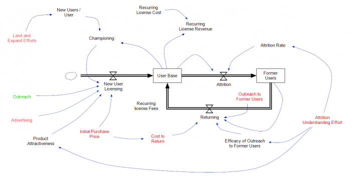
You can bend arrows to route them around other nodes or distinguish them more clearly. Bent arrows can be either segmented -- a sequence of straight lines -- or curved. In either case, they have a series of vertexes or way points. Curved arrows are drawn as cardinal splines through the way points', which determine the shape. You can also set arrows' thickness, style (solid, dashed, or double line) and color.

The drawing above uses arrow styles with conventions for "systems dynamics" models, quite a bit different from the default Analytica styles. Many of the influence arrows have been curved and colored blue. One arrow is segmented, with a double-line style and increased line thickness. The boundaries and fill for most the variables have been turned off, and three variables contain an icon that looks like an hour glass and have labels turned off, one has a icon resembling a cloud.
To bend an arrow, first click the arrow to select it. Two handles appear near its midpoint: a round handle for creating a curved arrow and a square handle for creating a segmented line. Drag either handle to introduce the first way point.
When you select an arrow, its way points appear as solid black handles. Each segment has gray handle at its midpoint that you can drag to introduce another way point.
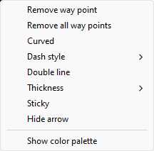
To remove a single way point, right-click on a black way point handle and select Remove way point.
To convert a segmented arrow to a curved arrow, or vice versa, toggle Curved on the right-mouse menu.
Changing an arrows appearance

Click an arrow, and right-mouse click to see the right-click menu. You can select a dash-style for an arrow, change its line thickness, or change it to draw as a double-line.
To change the color of an arrow, show the Color palette from the Diagram menu, select the arrow, and click a color in the color palette.
Sticky arrows
When you enter a Definition for the first time, or change an existing Definition (or other expression attribute), Analytica adds or removes incoming arrows to reflect the actual dependencies. In some cases, you might want an arrow that you've drawn to remain even if there is not an actual dependency. We call this a sticky arrow. Select (or de-select) Sticky on the right-click context menu to make an arrow sticky. Sticky arrows are sometimes useful for documentation. An arrow that does not reflect a true dependency displays with a dashed line style unless you've set the dash style explicitly.
Hiding an arrow
Occasionally you may want to hide a particular arrow that appears due to Analytica's default rules that decide when to show an arrow. To hide an arrow, select it, right-click to show the context menu, and select Hide arrow.
If you decide you want to later show the arrow, you'll need to select it by clicking in the right place. This may be challenging since you can't see it and have to remember where it is! This is easier to do for arrows without way points, or at least for non-curved arrows, so you might consider uncurving or removing way points before hiding. Once you've successfully selected it, right click on a way point or segment midpoint and select show arrow from the context menu.
See Also
- Draw arrows between modules
- Tutorial: Drawing arrows between variables
- Tutorial: Drawing arrows between nodes
- GetArrowsOnDiagram
- Model building by mouse
- Definitions
History
- Segmented and curved arrows, and the ability to change line width, styles, and colors, were introduced in Analytica 6.0
- Sticky arrows introduced in Analytica 6.3
- Using dashed lines for arrows that don't reflect a true dependency introduced in Analytica 6.3.


Enable comment auto-refresher